Skype is one of the largest VoIP providers with over 500 million users. Skype was created by the developers of KaZaa and unlike many of its competition; it operates on a P2P overlay network (It is not using the IETF Session Initiation Protocol (SIP)). Because of its popularity and proprietary design, there has been a surge in the research community and the industry to understand its architecture and network traffic.
From these research, we know that Skype uses wide-band codec (iLBC, iSAC and iPCM developed by GlobalIPSound) which allows it to maintain reasonable call quality at an available bandwidth of 32 kb/s (The Skype claimed bandwidth usage of 3-16 kilobytes/s) and the minimum and maximum audible frequency Skype codec allowed to pass-through are 50 Hz and 8,000 Hz respectively. Note that Codecs are automatically selected. However, as described in [1], it is possible to force Codec selection enclosing the list of disabled Codecs between the tag
In addition, Skype uses TCP for call signalling, and both UDP and TCP for transporting media traffic. Moreover, Skype uses 256-bit AES (Advanced Encryption Standard) encryption and 1024 bit RSA to negotiate symmetric AES keys. User public keys are certified by the Skype server at login using 1536 or 2048-bit RSA certificates.
In this article, I describe the key features of this software.
There are common terms which are used in the Skype literature and I would like to define them before we start:
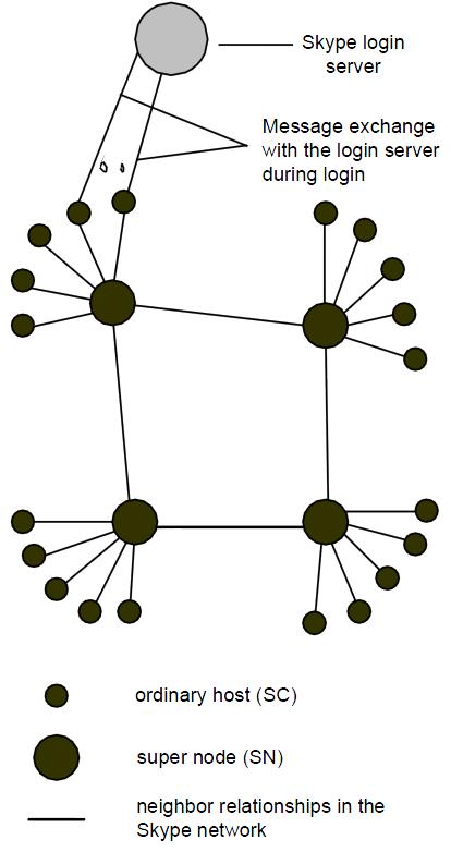
Skype Client (SC): Skype application which can be used to place calls, send messages and etc. The Skype network is an overlay network and thus each SC needs to build and refresh a table of reachable nodes. In Skype, this table is called host cache (HC) and it contains IP address and port number of super nodes. This host cache is stored in an XML file called “shared.xml”. Also, NAT and firewall information is stored in “shared.xml”. If this file is not present, SC tries to establish a TCP connection with each of the seven Skype maintained default SNs IP address on port 33033.
Super Node (SN): Super nodes are the end points where Skype clients connect to. Any node with a public IP address having sufficient CPU, memory, and network bandwidth is a candidate to become a super node and a Skype client cannot prevent itself from becoming a super node. Also, if a SC cannot establish a TCP connection with a SN then it will report a login failure.
Skype Authentication Server: This is the only centralized Skype server which is used to authenticate Skype users. An authenticated user is then announced to other peers and buddies. If the user saves his/her credentials, authentication will not be necessary. This server (IP address: 212.72.49.141 [Buddy list] or 195.215.8.141) also stores the buddy list for each user. Note that the buddy list is also stored locally in an unencrypted file called “config.xml”. In addition, if two SCs have the same buddy, their corresponding config.xml files have a different four-byte number for the same buddy. Finally, it has been shown that Skype routes login messages through SNs if the authentication server is blocked. [Refer to [3] for more details]
Start of Message (SoM) Structure: Skype uses the same port to communicate with the outside world. Therefore, it needs an unencrypted structure in the beginning of each UDP packet to analyze the sequence and the flows at the application layer. This structure is called SoM.
Now let’s analyze the services offered by Skype and its network traffic.
Types of Skype Connections
Skype to Skype (End to End) (E2E)
Call signalling and media transfer
- If both caller and receiver are on public IPs and receiver is in the buddy list of the caller, then they establish a call through a direct TCP connection with each other and transfer media using UDP.
- If the caller or receiver is behind a port-restricted NAT then they establish a call through a few packets initially transferred between caller, receiver , SN and other hosts [Refer to [3] for more details] and a UDP connection is established between the caller and receiver which is used to transfer media as well.
- If caller and receiver are behind a UDP-restricted firewall they will need a relay (node) in between to establish TCP connection to and then the traffic (including media) will go through from one side to the other.
For users that are not present in the buddy list, call placement is equal to user search plus call signalling.
The media structure for E2E is as follows:
- SoM
- First 16 bits are the message identifier which is chosen similar to TCP (random and confirmed by the receiver).
- Function byte (3 random bits + 5 bits) which defines the payload. The random bits can be removed by applying ox8F bit mask.
- Skype login phase or connection management
- 0x02: Skype UDP Ping is carried out periodically by all the SCs which consist of two keep-alive messages.
- 0x03
- 0x07
- 0x0f
- 0x0d indicates a DATA message.
- Frame ( Encrypted )
Skype to PSTN (Public Switched Telephone Network) (SkypeOut)
For Skype out, the application initially contacts the SN and then the PSTN gateway at port 12340. The gateway servers are a separate part of the architecture and not a part of the overlay network. In addition, host servers 195.215.8.140 and 212.72.49.155 are only connected when a user tries to call another user in the PSTN network; therefore, we assume these servers to be Skype-to-PSTN gateways (SkypeOut) [4]. Also, in [1], it is described that G.729 Codec is the preferred codec for E2O (Skypeout) calls.
- SoM
- The first 4 bytes seems to be a unique Connection IDentifier (CID).
- Frame ( Encrypted )
PSTN to Skype (SkypeIn)
Skype Network Traffic
Skype UDP Ping
Skype UDP Ping is carried out periodically by all the SCs which consist of two keep-alive messages.
Skype UDP Probe
Message exchange is used when the Skype is launched and it is used to discover available SNs and network characteristics such as NAT and firewalls. [Refer to [2] [3] for more details]
Skype TCP Handshake
After finding an available SN, SC opens a new port and creates a TCP connection to the SN (On the same port number as the Probe was sent). If an arbitrary port will not be able to go through the NAT or firewall, then SC will use port 80 (Proprietary HTTP protocol handshake) or port 443 (Transport Layer Security [TLS] HTTPS protocol handshake) to connect to the SN. [Refer to [2] for more details]
Skype TCP Authentication
After setting up the connection, a SC connects to the Authentication Server to authenticate itself. [Refer to [2] for more details]
Skype HTTP Communication
On the first execution, it sends an HTTP request to skype.com with the keyword “installed” in it. Also, this is used to retrieve software updates with keyword “getlatestversion”. [Refer to [2] [3] for more details]
Skype User Search
Skype uses its Global Index (GI) technology to search for a user. Skype claims that search is distributed and is guaranteed to find a user if it exists and has logged in during the last 72 hours. Due to the fact that the search messages between the SC and SNs are encrypted and the protocol is not open, it is not possible to make any conclusion about the search techniques used by Skype. But from the response time for each search, we can conclude that there is some sort of user information caching in SNs.
Skype Silence Suppression and Call Hold
Skype does not any sort of Silence Suppression and continues sending silent packets and keep-alive messages during a call hold. Note that this will maintain the UDP binding at NAT, provide some background noise during silence and avoid the drop in TCP congestion window size (when a TCP connection was made between caller and receiver).
Skype Conference Calling
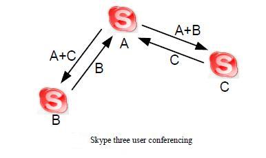
During a conference call, the most powerful machine always gets elected as a conference host and the other two clients send their data to that host as depicted in the diagram.
References:
- Bonfiglio, D., Mellia, M., Meo, M., Rossi, D., Tofanelli, P.: Revealing skype traffic: when randomness plays with you. SIGCOMM Comput. Commun. Rev. 37(4), 37–48 (2007)
- D. Adami,C. Callegari,S. Giordano,M. Pagano,T. Pepe – A Real-Time Algorithm for Skype Traffic Detection and Classification – S. Balandin et al. (Eds.): NEW2AN/ruSMART 2009, LNCS 5764, pp. 168–179, 2009.
- Baset, S.A., Schulzrinne, H.G.: An analysis of the skype peer-to-peer internet telephony protocol. In: INFOCOM 2006. 25th IEEE International Conference on Computer Communications, pp. 1–11 (2006)
- S. Ehlert, S. Petgang, T. Magedanz, and D. Sisalem, “Analysis and signature of Skype VoIP session traffic”, CIIT 2006: 4th IASTED International Conference on Communications, Internet, and Information Technology, 2006, pp. 83–89.

Thank you for posting this Mohammad.
I’d like to clarify one concern about the Skype architecture. Is there any intermediate storage of the instant message content, whether on SCs, SNs, or the central Skype [login] Server? Or is this content delivered point to point, without intermediate storage. This is a crucial point of concern for me.
Thank you for taking the time to respond.
Dave
Sorry for the delay. I am not aware of any caching done on the intermediate nodes. From the security standpoint, note that any node can capture the network traffic passing through them. Therefore, in theory, a super node can capture the traffic belonging to the child nodes and break the encryption. Although, this is possible, it is an extremely hard task and highly unlikely.
Thank you for providing detailed description along with the diagrams and illustrations which are a real help.
Hi! I was looking for information on Skype Network Traffic and I must say that you have presented it quite well in the blog. Thanks a lot!